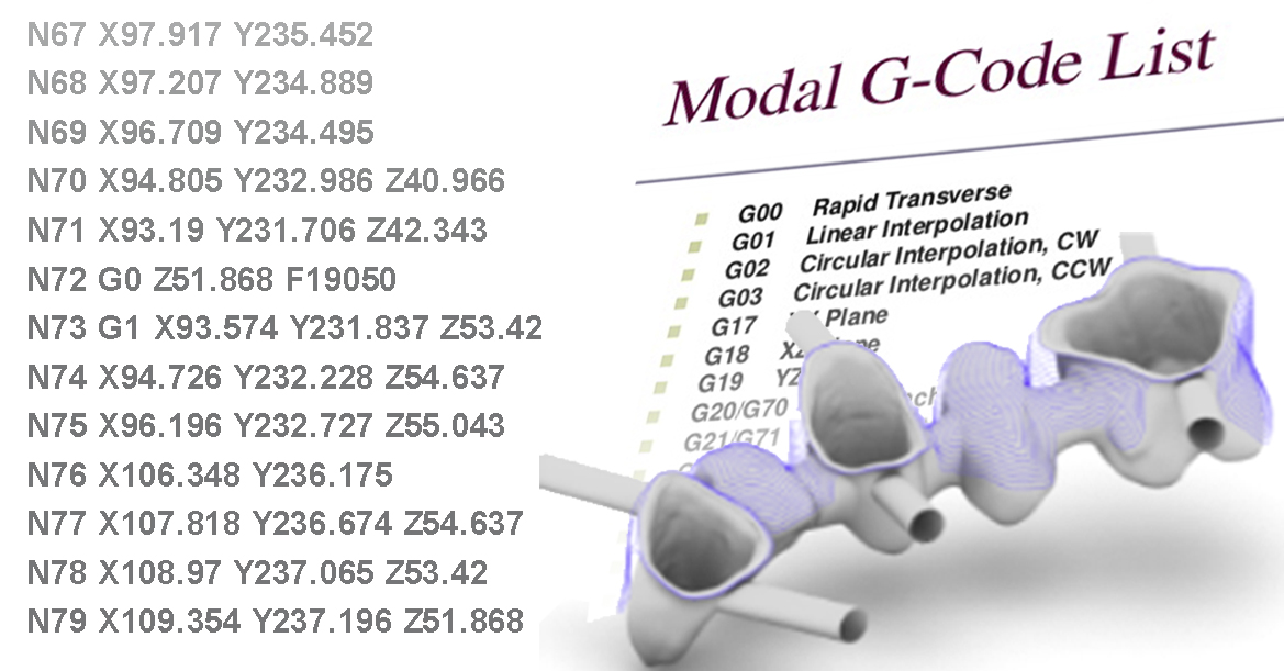
G-code is the generic industry term for the computer language that most CNC machines use to control their movements and how they make parts.
What might come as a surprise is that machining centers do not have the concept of the part or restoration being made. A CNC machine only understands the commands provided via the G-code commands.
G-code is most typically created as the output from CAD/CAM (computer aided design/computer aided manufacturing) software.
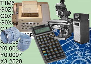
G-code is also commonly referred to as NC code stored in a NC file or, in a throw-back to the early days of punched tape—a Tape file. This code is the foundation for communicating with both industrial CNC's and your Dental Machining Center.
G-code is generated by a translation program called a post-processor. It is the very important job of the post-processor to translate the motion you see on the computer screen into G-code language that it understands so that the machine can execute the G-code and produce your restoration.
The basic format of a G Code statement is called Word Address Format. This means each command is made up of “words” and associated parameters for the "word". Some "words" provide motion such as G00, G01, other "words" such as G21, set operational conditions. G is the address of the word. It says to the machine control, “look at your list of ‘G’ commands, pick command number 21 and get ready to do it.” This particular command (G21) tells the controller to interpret distances as millimeters.
G-code is written in ASCII text and typically stored in a man-readable ASCII textfile that is able to be opened and read in any standard text editor such as: Notepad, Wordpad, Microsoft Word, etc. G-code provides the commands which which are typically strung together in "blocks" that your machine will execute.
CNC Machine Fundamentals: The Versamill will only perform the commands contained in the NC (G-Code) file. Ultimately, this is THE file which runs the Versamill.
To provided a basic foundation, let's look at the most popular commands.
G0 - Machine Rapid: Move to a location at the maximum speed the machine is tuned for. Example: G0 X23.5 Y 17.8 Z 12.7 -> Move to upper right corner of a (12 mm) puck, .7 mm above the top surface.
G1 - Machine Feed: Move to a cartesian coordinate at the programmed Feedrate (normal cut condition).
F - Requested Feedrate expressed in mm/min
Machines such as the Versamill DMC's will perform automatic accelleration and deacceleration to properly follow the requested coordinates. Programming a feedrate does not guarantee that the machine will actually move at that rate, which is a good thing on quality CNC's
Example:
G1 X-15.23 Y -1.2 Z 11.8 F 1500
Move 15.23mm left of the puck center, near the Y centerline (1.2mm below), 0.2mm deep into a 12mm puck (Z-axis 0 location being the bottom of the puck) at a feedrate of 1500 mm/min. Since the X, Y, and Z coordinates appear on the same G1 or G01 (move at feedrate) "block" the three axes will move simultaneously to reach their end-points at the same time before moving on to execute the next 'block" in the part program.
You can find out more indepth information on G-codes here. This link will provide a list of G-codes, their function, how they work and the associated parameters required with ehach code.
 It's interesting to note that many Axsys Inc. associates' experience dates back to actually having to hand-write these codes utilizing teletype machines and punching paper or mylar tape that would be read into either an NC machine via tape reader for block-by-block execution or into a CNC machine that would read the instructions on the paper tape and store the part program into a limited machine memory.
Coordinates for machine axes end-points were determined by reading a 2-dimensional blueprint and, using triginometry, calculating the X, Y and Z end-point/tangency value and typing the "word" such as "X" followed by the calculated value, "Y" followed by the calculated value and Z, followed by the calculated value (or required value if a 2D program).