Calibration & Your Versamill 5X DMC: Part 2
In Part 1 of our series we investigated the symptoms of calibration related problems and reviewed when a milling center can benefit from calibration "tuning".
In Part 2, we will explore what is 'behind the panels' and offer additional techniques for fine-tuning your Versamill.
Please read and understand any recommendations provided. Failure to adhere to the recommendations can severely affect the 'Cut Quality' of your milled units.
In extreme cases, there is also the possiility of machine collisions, broken tooling burrs, and damaged components.
Laying the foundation
At the heart of a DMC are the primary components required to facilitate a consistent and stable calibration.
- Rigid frame to hold sub-components.
- Linear rail to accurately transmit motion to the isolated or composite axis.
- Rotary servo or stepper motor to transmit given commands to physical movement.
- Ballscrew or rotary reduction to convert rotary motion to linear motion.
- Spindle, Spindle Collet, and Quality of tooling.
Accuracy of the overall system is considered a constant given the success and quality of components utilized above which is typically sub-5µm for Versamill 5X machines.
What the Versamill Machine Calibration is Tuning.
The calibration itself does not modify any of the design components above. Instead, the calibration is tuning the relationship between the stated components and the fixture (material) in absolute coordinates.
Or, to state in another context. The calibration modifies the G55 Cartesian Coordinate system to align with the center of the fixture location.
Pro Tip: Record or Screenshot the axis values before and after fixture offset adjustments. This will allow you to compare the results and determine the exact differences in the calibration.
When running an NC Program on your DMC one of the first lines in the program will be the 'G55' command which is telling the machine to use the fixture calibration values.
With Versamill 5X-Series machines being full continuous 5-axis machines, this requires additional parameters: X, Y, Z, A, B
Let's break down what the values are doing.
- A/B : Adjusting angular values to start material perpendicular to the tool bur.
- Z - Identify absolute center of material.
- X,Y - Adjusts center of rotary axes.
A/B Rotation Errors
For traditional manufacturing involving CAD/CAM discs, minor errors in the A/B rotation have little impact to the overall results and are typically difficult to detect. These errors will present themselves on cases where the overall case thickness is very close to the overall puck thickness where the case may not fall entirely within the disc.
When nesting cases which are close to the overall disc thickness, most clients prefer to leave a small amount of material between the bottom of the preps and bottom of disc.
Given any errors in calibration, worst case scenario is the occlusal may have minor scalping but the margins/implants will maintain their integrity.
Other operations that can identify an A or B-axis rotation error occur when engraving text on the top of the blank disc to identify units during cutout. Text may illustrate as deeper, or lighter, than intended.
The most significant area of concern is while milling titanium abutments which require very precise locations. On the 5X200, an A-axis error might present as misalignment for positions (P1-P3, P4-P6) on the interface in the +/- Z-axis direction (offset).
B-axis errors would appear similar but the deviation will present on (P1,P3,P4,P6).
While the single-unit block fixture is similar, most customers will not experience any difficulty.
Z-Axis
The Z-axis calibration adjusts the spindle offset from the reference, home position— including the tooling bur to the center of material.
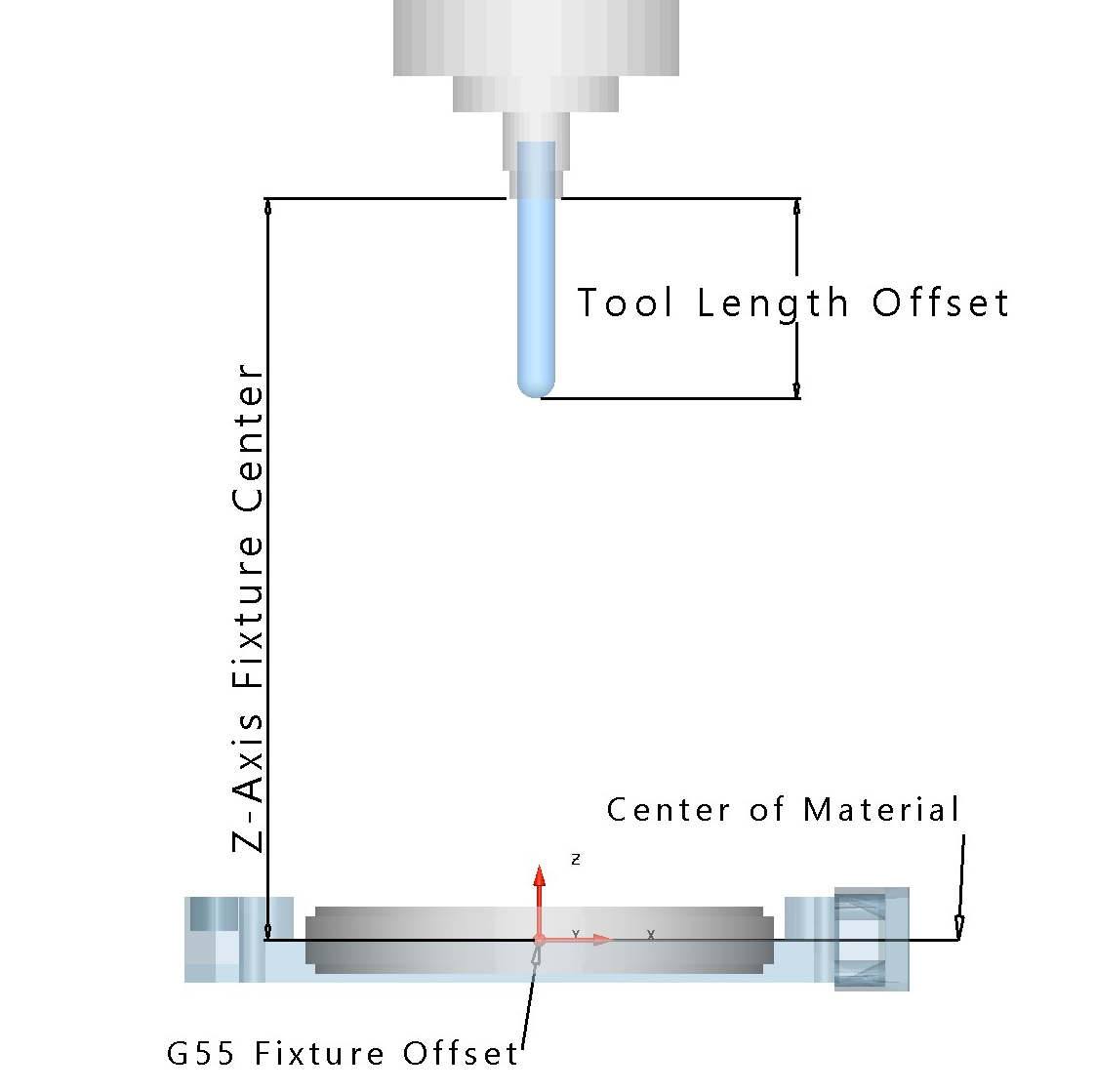
The image above illustrates a standard configurationutilized by many dental mills.
For the mill to "understand" where the fixtured material is located, reference data is loaded into the G55 Fixture Offset Register which, as discussed in Part 1, stores the referenced calibration data.
The spindle is illustrated in the "Home" position. Looking at the illustration, the "Z-axis fixture center value" represents the "offset" or the amount of distance required for the spindle nose, in the "Home" position to reach the material Z-Zero location.
Also shown in the illustration is the "Tool Length Offset" which represents the distance the cutting tool sticks out beyone the spindle "nose". This distance is dependent on the overall length of tool being utilized for a specific milling operation. On dental milling centers this is distance is typically determined automatically by use of a touch probe sensor.
Armed with the fixture center and tool length values, the machine control can now identify where the material center is. This value is then utilized to execute G-Code commands in the appropriate cartesian coordinate system.
Before troubleshooting Z-Axis errors, please make sure to clean the tool touch sensor. Debris and buildup on the tool sensor will effect the overall accuracy, similar to using heavy spray on scanned models.
Identifying a Bad Z-Axis Calibration
For this example, an arbitrary value of .075 mm will be used to represent the amount of error in our Z-axis calibration.
If this error is in the positive direction this would mean that when we command the mill to cut at the center of the material disc (Z = 0.0) we would instead be cutting at a center of the disc + .075 mm instead of the proper Z 0.0.
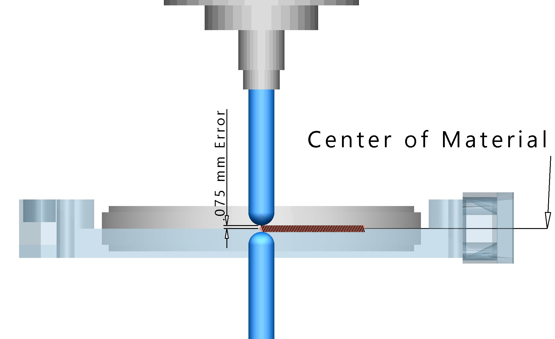
Now, when the disc is rotated 180° and the same Z=0.0 position location is commanded, the same positional error occurs resulting in an overallerror of 0.15 mm.
Referring to the illustration above, the image shows the tip of tooling burr at at Z = 0.0, both an A-axis = 0° & A-axis = 180° rotation. The area where the tools do not properly meet the center equates to the amount of stock or additional thickness that would appear in the units that are milled.
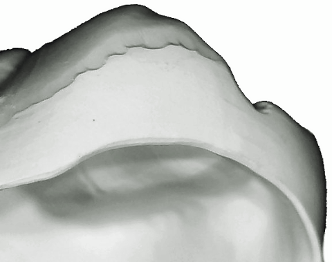
Applied to a unit which has a 8.76 mm overall height. The final milled unit would measure as much as 8.96 mm, resulting in a thicker than desired unit.
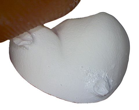
If the error was a negative .075mm, the end result would be a unit that could measure as much as 8.56mm. This error typically results in a hole, or very thin wall between the prep and occlusal surface. Take a moment to consider the minimum thickness value that you design the unit with in your CAD software. Now subtract 2 times the error. How will that affect the final milled result?
One last point of note: Due to the sensitive behaviour of a Z-Axis calibration, simultanious 5-axis motion can signficantly impact all regions of your milled restoration. When affected by a Z-Axis error, the tooling burr is no longer in the proper location and conditions such as "over-milling" and "under-milling" will be geatly amplified.
Pro-Tip: If fighting fit issues and your CAM strategy utilizes simultanious 5-Axis operations for finishing, minimize the potential issues by selecting a 3+1 strategy for troubleshooting until the problem has been identified.
X,Y Axis Calibration
Now that we understand the Z-axis adjustment, The same basic principle applies to the X,Y axis. The only difference is direction. Instead of using the spindle home reference, the reference distance is measured from the X or Y-axis "Home" position to the center of the A or B rotational axis.
Consider our first "bad" example with a misalignment.
Approximate error is around 0.15 mm which converts to a .075 mm adjustment which is calculated as: ((Current axis reference position) - (Error/2)).
By syncronizing the axis in error with the rotation axis, the height of contour offset quickly vanishes.
To recap: In Part 1 of our series, we illustrated symptoms of a bad calibration and identified when a calibration might enhance the quality of your milled units.
In Part 2, The "background" behind a calibration is presented, along with additional symptoms of specific calibration errors.
Stay tuned for Part 3 where we discuss Pro Tips for enhancing your automated calibration even further.